 Pomanique Electric Co., Ltd.

Product Overview
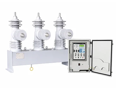
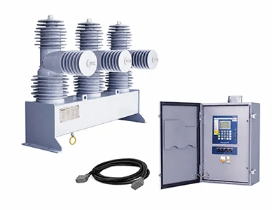
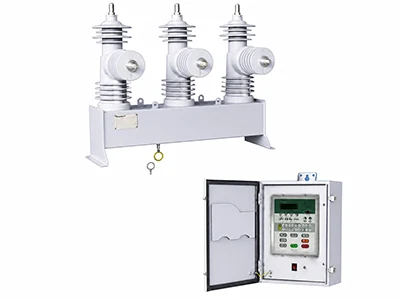
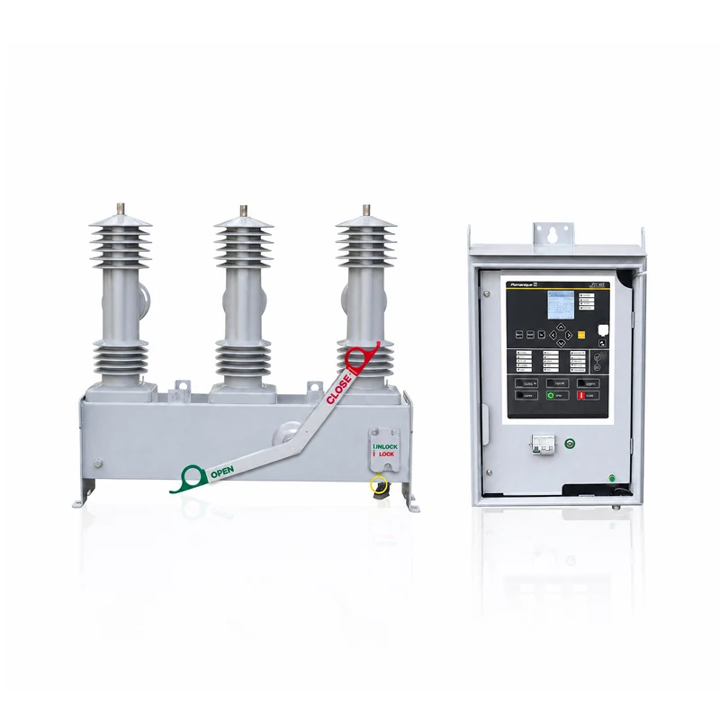
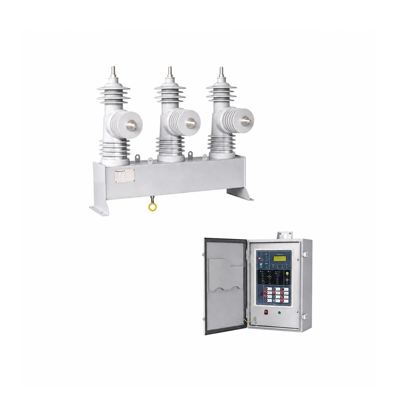
The Microprocessor Based controller provide protection, control, monitoring, instrumentation and metering with integrated input and output logic, data logging & fault reports.
Communication access to controller functionality is via electrical RS485 port for remote connection. Additional rear port options including RS232 port is available.
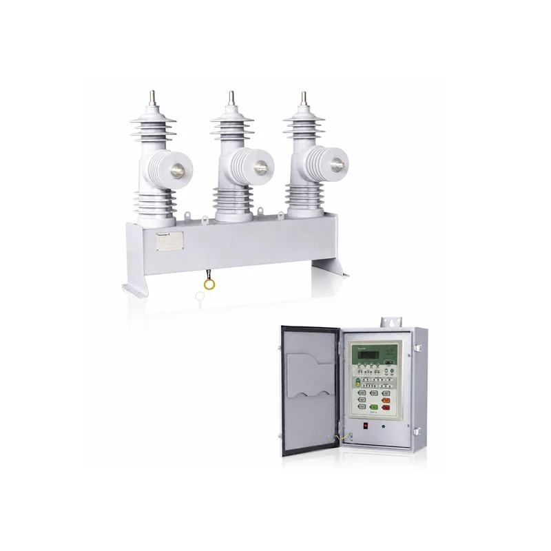
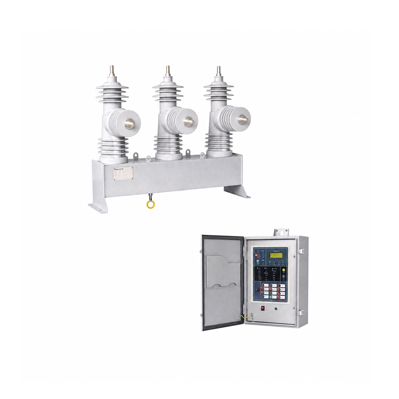
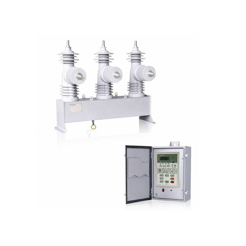
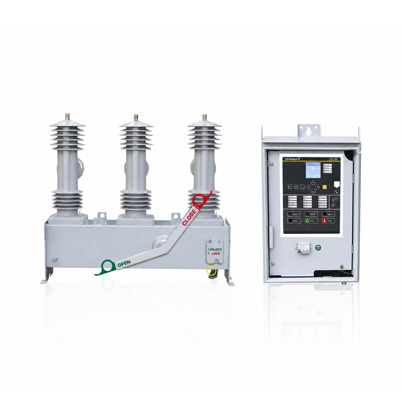
The controller is mounted in the control cubicle. Along with the controller, this cubicle also contains the auxiliary power supply with batteries for uninterruptible power supply, electronic boards and circuit breakers.
The cubicle includes the complete electronics, the protection relay and the UPS system of the recloser. Additional components and features can be selected via order.
The controller contains a large number of protection functions (elements) which can be selected or deselected through the menu driven display.
Key Features
Analysis of current/voltage normal & negative sequence for power quality monitoring.
Recording of PQM with fault waveform of 128 sampling and 20 cycles.
Harmonics analysis of electric data.
Monitoring of Sag, Swell, Interruption, over & low voltage, unbalance and etc.
Improvement of fault detection algorithm.
Automatic isolation of faulted section site and interconnection with other healthy section.
Improved measuring accuracy
Multi-Protocol support. (DNP3.0, MODBUS,IEC60870-5-101/104 & IEC61850).
User programmable logic(PLC) support.
Get an FTU-R200 quote for your project
Share your protection requirements, communication interface and control-cubicle needs with Pomanique. Discuss the FTU-R200 configuration and request a project quotation.
Request an FTU-R200 QuoteParameters
Technical specifications
General Protection Features
Operating sequence
| Sequence / description |
|---|
| Reclose times are selectable. The operating sequence is defined by: |
| O – 1st rt – CO – 2nd rt – CO – 3rd rt – CO |
Reclose times
| Parameter | Value / description |
|---|---|
| 1st Reclose Time range: | 0.3 – 600 sec |
| 2nd Reclose Time range: | 1.0 – 600 sec |
| 3rd Reclose Time range: | 1.0 – 600 sec |
| Timing resolution: | 0.1 sec |
Phase & Ground Fault
| Parameter | Value / description |
|---|---|
| Pickup Level : | 10~2000A (step:1A) |
| Fast TC Curve : | 50 types (ANSI,IECmRecloser) |
| Fast Multiplier : | 0.05~2.00 (step:0.01) |
| Fast Time Add : | 0.00~1.00 (step:0.01sec) |
| Fast Min Response : | 0.00~1.00 (step :0.01sec) |
| Delay TC Curve : | 50 types (ANSI,IECmRecloser) |
| Delay Multiplier : | 0.05~2.00 (step:0.01) |
| Delay Time Add : | 0.00~1.00 (step:0.01sec) |
| Delay Min Response : | 0.00~1.00 (step :0.01sec) |
Direction Detection
| Parameter | Value / description |
|---|---|
| 3V1 threshold : | 0~100% (step:1%) |
| 3I1 threshold : | 0~100% (step:1%) |
| 3I1 Angle : | 0~359° (step:1°) |
High Current Trip (HCT)
| Parameter | Value / description |
|---|---|
| Phase-HCT Pickup Leve : | 25~10000A (step:1A) |
| Phase-HCT Adder : | 0.01~1 (step:0.01sec) |
| Ground-HCT Pickup Level : | 25~10000A (step:1A) |
| Ground-HCT Adde : | 0.01~1 (step:0.01sec) |
Delay Time Current Trip
| Parameter | Value / description |
|---|---|
| Phase-HCT Pickup Leve : | 25~10000A (step:1A) |
| Phase-HCT Adder : | 0.01~2 (step:0.01sec) |
| Ground-HCT Pickup Level : | 25~10000A (step:1A) |
| Ground-HCT Adder : | 0.01~2 (step:0.01sec) |
Sensitive Earth Fault (SEF)
| Parameter | Value / description |
|---|---|
| Pickup I0 : | 0.1~20A (step:0.1A) |
| V0 : | 10~80% (step:1%) |
| Operating Angle : | 0~345° (1°step) |
| Operating Time : | 0.1~30 sec (step:0.1sec) |
Cold Load Pickup/Inrush Restraint
| Parameter | Value / description |
|---|---|
| Cold Load Phase Pickup Multiplier : | 1.0~10 (step: 1) |
| Cold Load Time Duration: | 0~180 min (step: 1 min) |
| Inrush 2nd Harmonic Level: | 1~50% (step: 1%) |
| Phase, Ground, SEF Inrush Block : | 1 ( yes) / 0( no) |
Open Line (Loss of Phase) Detection
| Parameter | Value / description |
|---|---|
| Voltage On Level: | 50~90% (step: 5%) of rated voltage |
| Voltage Off Level: | 35~75% ( step: 5%) of rated voltage |
| Delay Time: | 0.1~30.0 sec (step: 0.1 sec) |
Synchronism Check
| Parameter | Value / description |
|---|---|
| Sync Fail Phase Difference: | 5~60°( step: 1°) |
| Delay time: | 0.1~30.0 sec (step: 0.1 sec) |
Under Frequency
| Parameter | Value / description |
|---|---|
| Pickup level : | 47.00~59.98Hz (step:0.01Hz) |
| Delay Time : | 0.03~10.00sec (step:0.01sec) |
Over Frequency
| Parameter | Value / description |
|---|---|
| Pickup level : | 52.02~63.00Hz (step:0.01Hz) |
| Delay Time : | 0.03~10.00sec (step:0.01sec) |
Negative Sequence Overcurrent(Broken conductor)
| Parameter | Value / description |
|---|---|
| Pickup I2 / I1 level : | 30.0 ~ 100.0 (step: 1%) |
| I2 / I1 delay time : | 0.01 ~ 100.0 (step : 0.01sec) |
4 Setting Groups
| Each group saves individual setting values |
| for different situations. |
| Parameter | Value / description |
|---|---|
| Active Setting Group Selection: | 1~4 |
Inter lock
| Live Load block |
| Sync fail block |
Recording
Events
| Totally more than 32,000 events are stored and listed. |
| I/O events (1024) / Functional events (1024,30000) / System events(256) |
| Fault events (256) /PQM event(256) / Demand profile I,P,Q (6144) /Maximum demand profile (1024) |
Fault Waveform
| Up to 4 faults are stored. (32 samples/cycle, 240 cycles/record) |
| Parameter | Value / description |
|---|---|
| Graphical Display in Analysis Tool : | Ia, Ib, Ic, In, Va, Vb, Vc |
Load Profiling
| Parameter | Value / description |
|---|---|
| Demand & Daily Maximum Current: | Ia, Ib, Ic, In |
| Demand & Daily Maximum Power: | kW, kVAR (A/B/C/3-ph) |
| Averaging Interval: | 5 / 10 / 15 min |
| Graphical Display in Analysis Tool |
| Parameter | Value / description |
|---|---|
| Local / Remote : | Control Position (only locally changeable) |
| Open/Close : | Switch Body Status Change Command |
| DO (Direct Operate) and SBO (Select Before Operate) are supported. |
| Parameter | Value / description |
|---|---|
| Reset : | Annunciator Manual Reset Command |
| Battery Test : | Battery & Charger Circuit Check |
| Protection Function Blocking |
| Parameter | Value / description |
|---|---|
| User Configurable DO Points (reserved) : | 2 |
Others
| Parameter | Value / description |
|---|---|
| RTC (Real Time Clock) : | YYYY/MM/DD hh:nn:ss |
| SOE (Sequence of Event) Time Resolution : | 1 msec |
| Digital Filtering & Dead-band Setting for Analog Inputs |
| Parameter | Value / description |
|---|---|
| Calibration (Correction Factor) : | Factory Setting only |
| Ia, Ib, Ic, In, Va, Vb, Vr, Vs, Vt |
| Parameter | Value / description |
|---|---|
| Factor Magnitude: | 0.500~1.500 |
| Phase Angle: | 0.000~359.9° |
Communication Interface
RS 232C #1
| On FRTU left-side (inside the inner door) |
| SCADA or DA System Communication Interface |
| Through Cable / Wireless / Fiber Optic Modems |
Functions
| Remote Operation (Control, Status Monitoring, Tele-metering) |
| Remote Setting (optional) |
| File Transfer (Event & Fault Data; DNP protocol only) |
Protocols
| DNP 3.0 (Level 2) or IEC60870-5-101 (optional) |
Baud Rate
| 1200 ~ 19200 bps |
Address
| Parameter | Value / description |
|---|---|
| Master Address: | 0 ~ 65534 |
| Slave Address: | 0 ~ 65534 |
RS 232C Port #2
| On FRTU Front Panel |
| Setting & Configuration, Maintenance, Recorded Data |
| Analysis Through Setting & Analysis Tool |
Functions
| Setting and Configuration Change (Batch Job) |
| Protocol Monitor (Communication Frame Check) |
| Parameter | Value / description |
|---|---|
| Real-time Display : | Measurement and Status Data |
| Event List and Fault Oscillograph |
| Demand Load Profiling & Graphical Display |
| FRTU Firmware Download |
Protocols
| Modbus |
Baud Rate
| 1200~19200 bps |
Connector Type
| DB9 Female |
Manufacturing
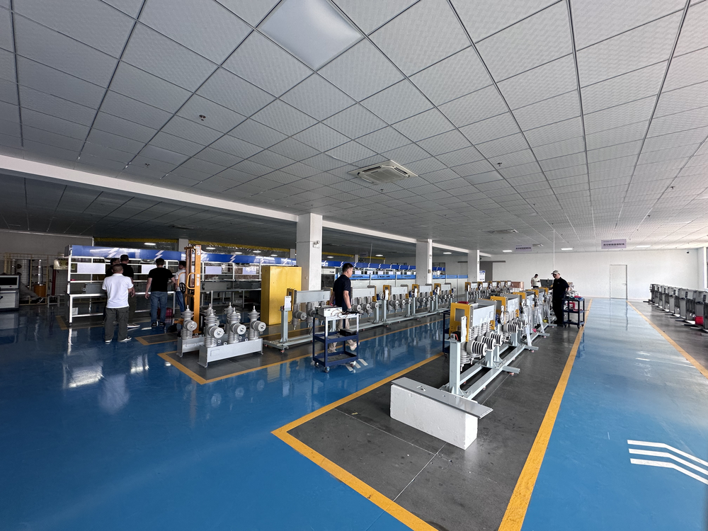
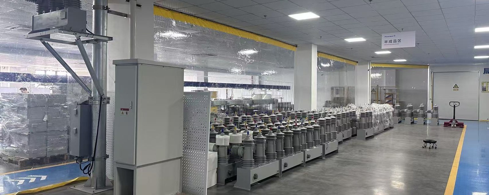
Production & quality control
Reception, production, testing and shipment areas are organized to keep technical requirements, work progress and delivery records aligned.
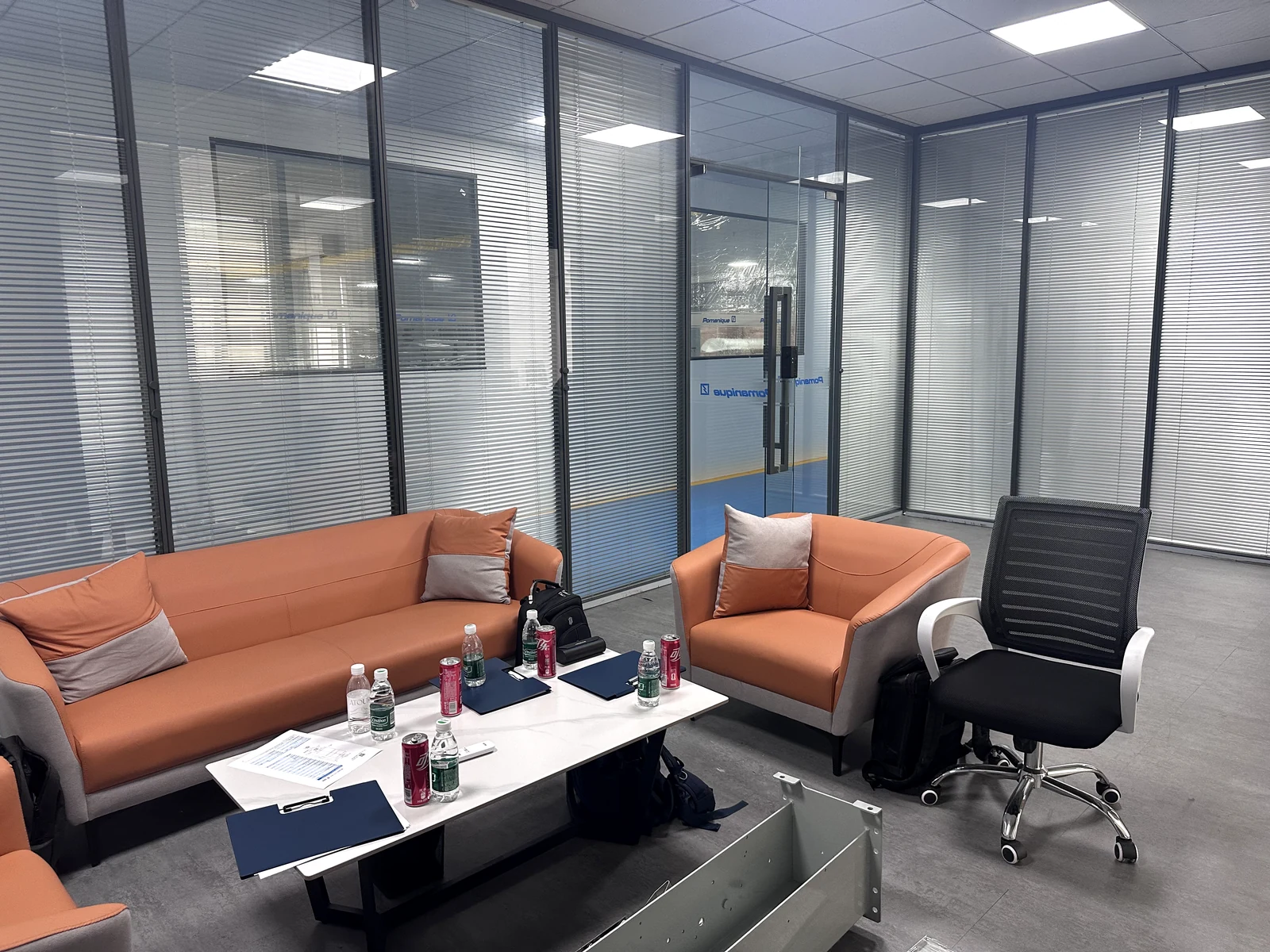
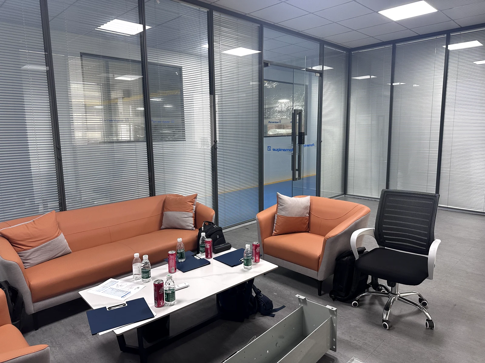
Workplace & Customer Reception
Visitors and project teams have a clear place to review requirements, drawings and delivery details before work moves forward.
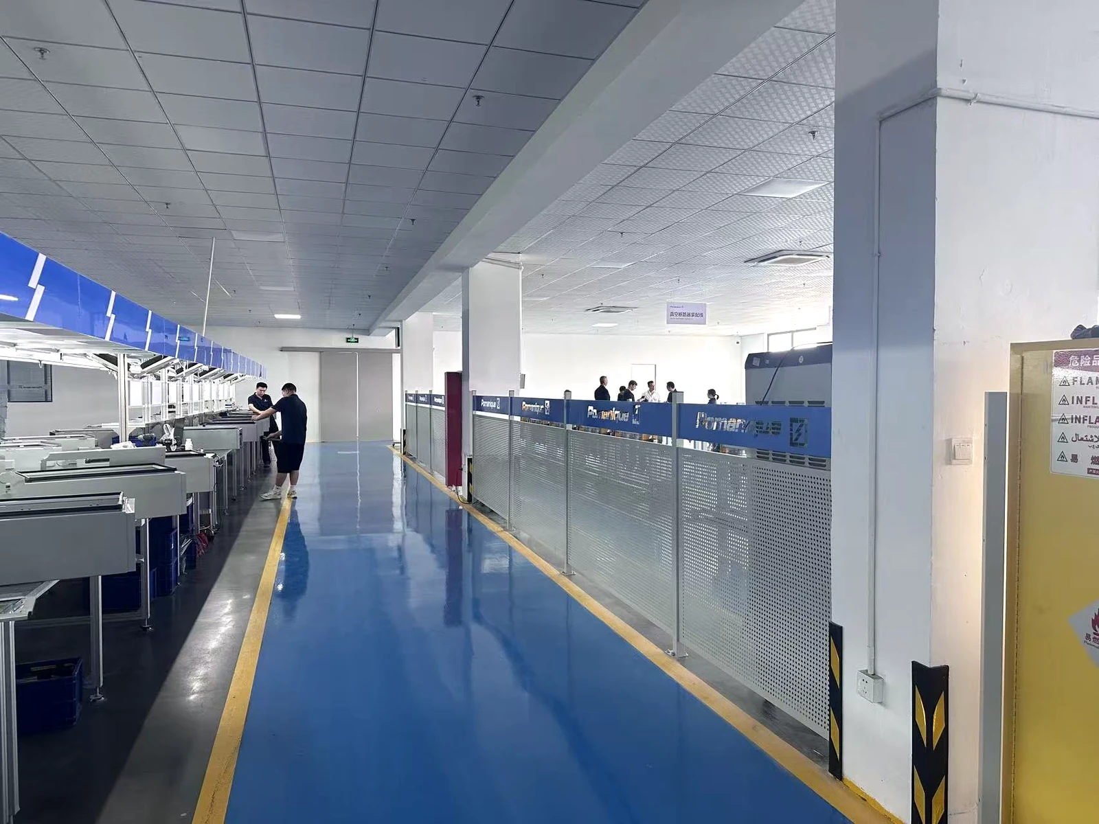
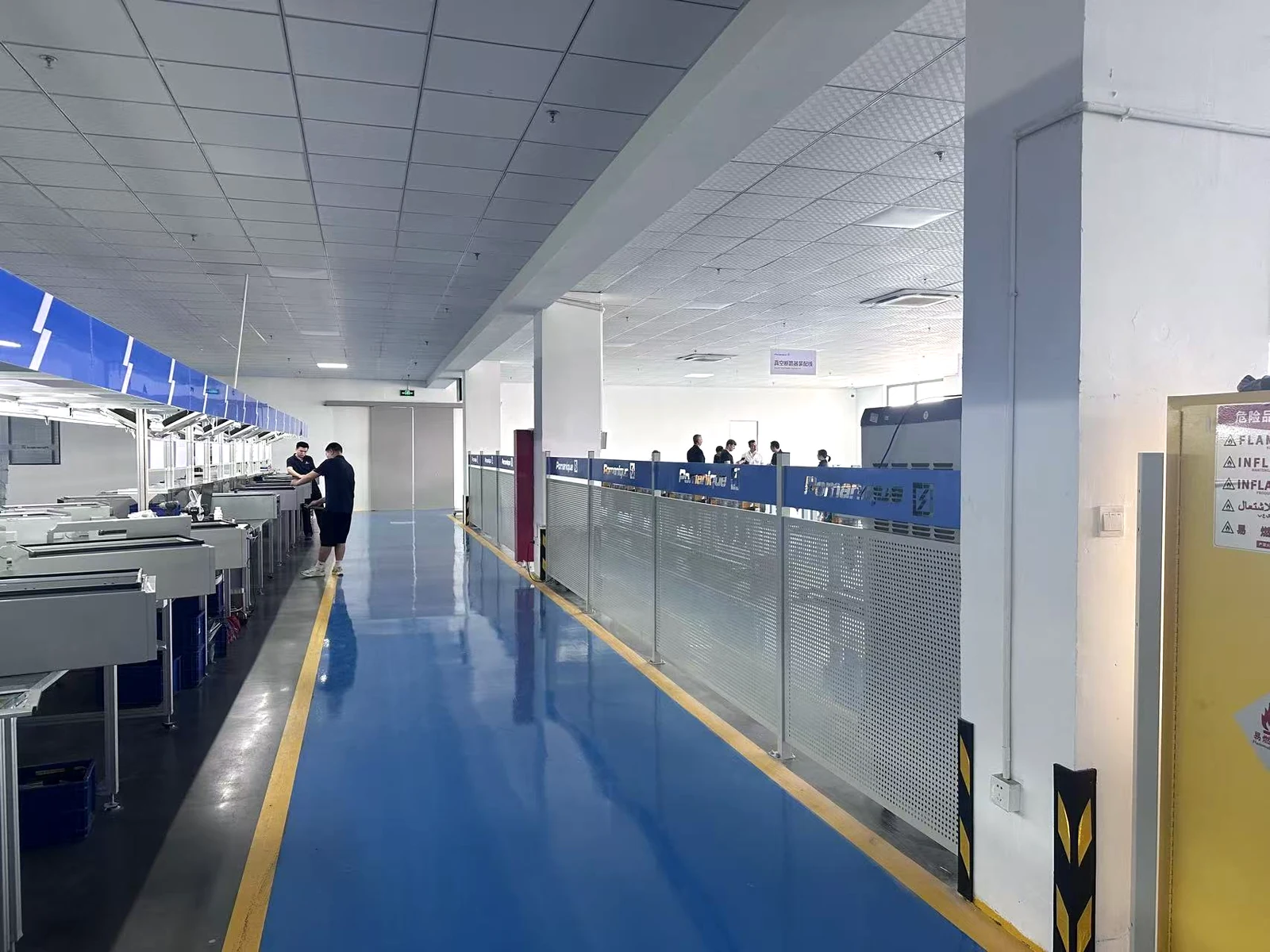
Organized Production Lines
Defined work areas and orderly material flow help teams keep assemblies, components and order information aligned.
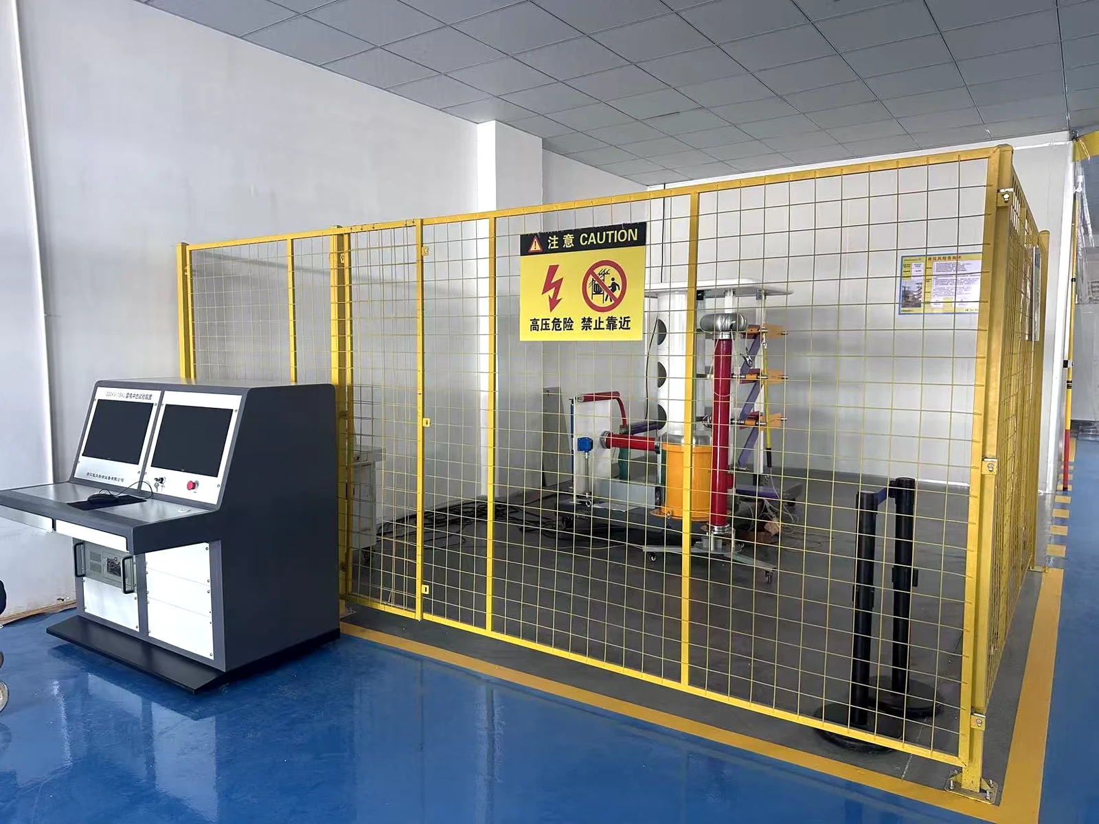
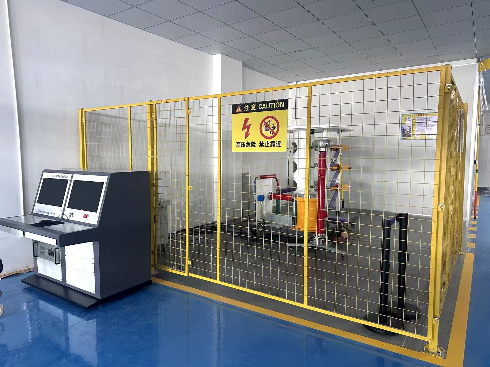
Testing & Verification
Routine checks and functional verification are completed against approved requirements before release.
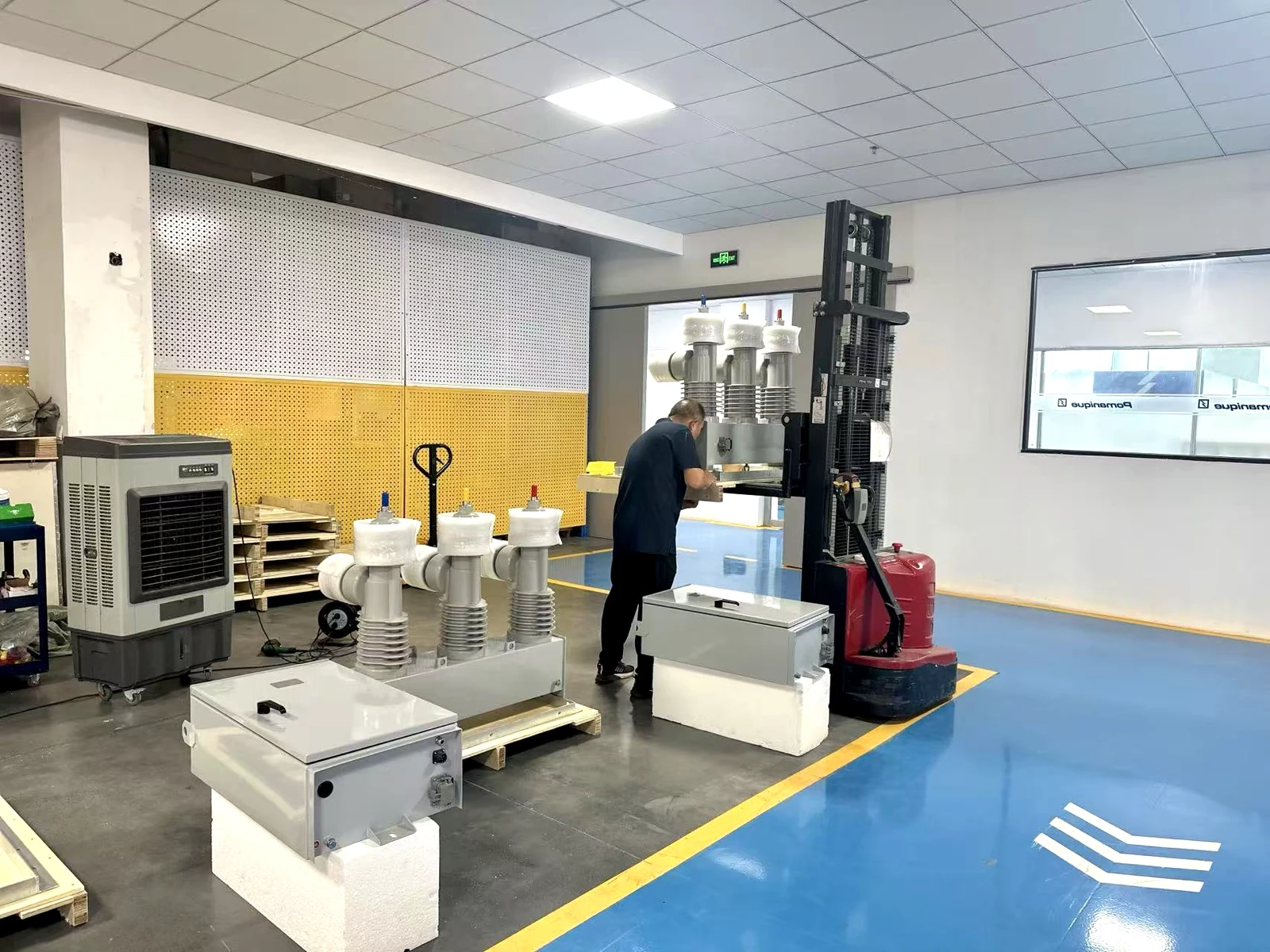
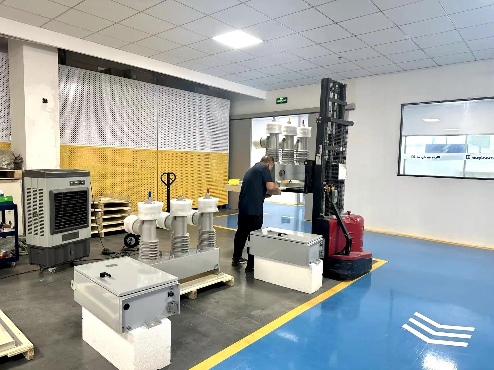
Shipment & Delivery
Finished orders are checked, protected and organized for traceable handover and coordinated dispatch.
Qualification & Certification
Built for recognised standards. Our documentation package supports project review with internationally recognised safety, quality and environmental marks.





About Pomanique
Pomanique Electric supplies medium-voltage switching, protection, insulation, control and transformer equipment for utilities, contractors, distributors and industrial projects.
Our product range covers reclosers, circuit breakers, load break switches, surge arresters, fuses, composite insulators, controls and relays.
Project requirements are reviewed before production, including ratings, installation conditions, interfaces and documentation. Assembly checkpoints, routine verification and final checks cover the agreed configuration, nameplates, accessories and packing before shipment.
More about Pomanique
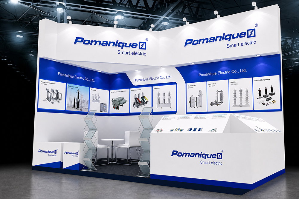
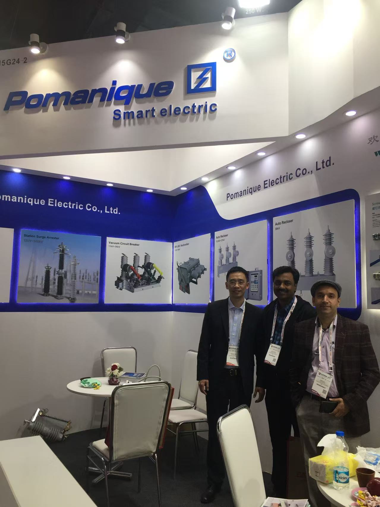
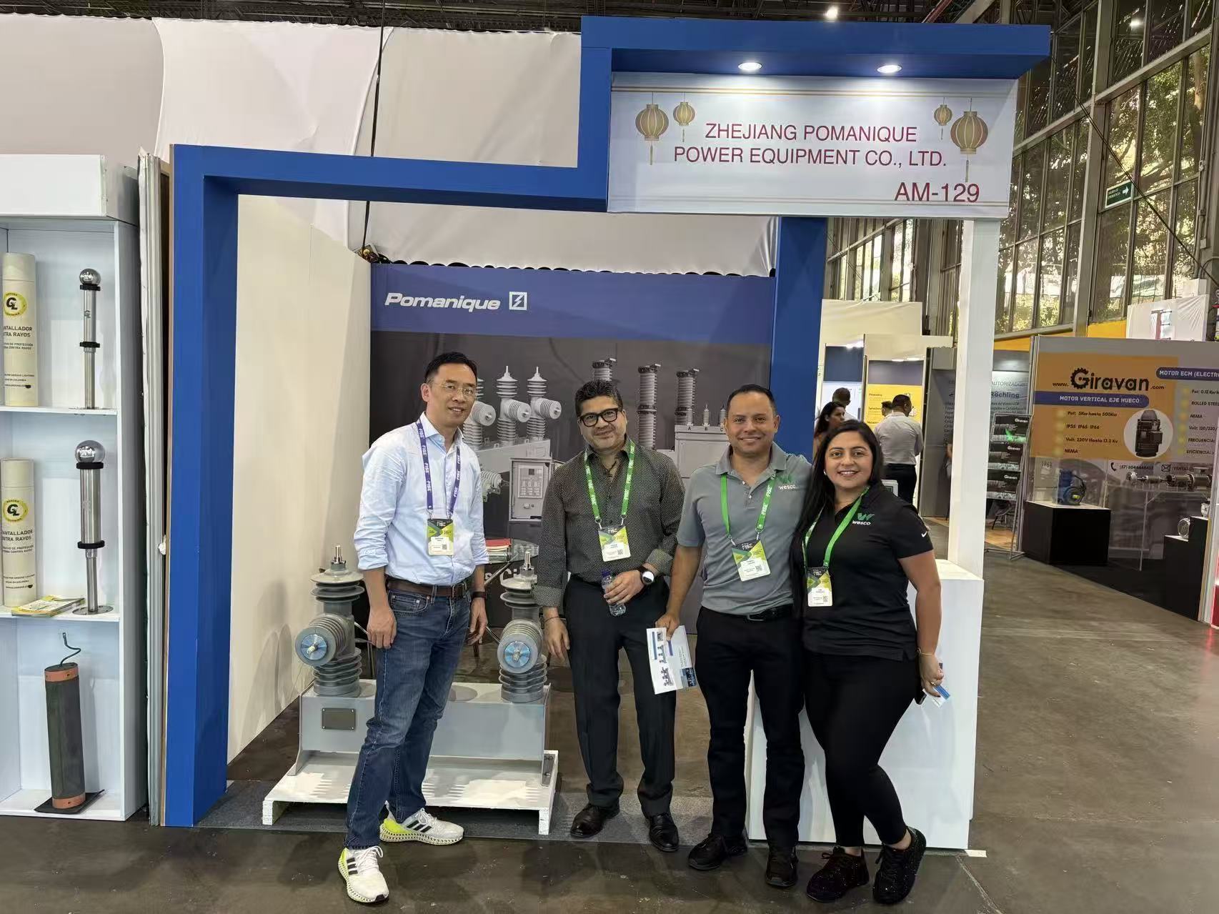
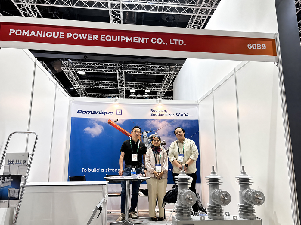
Exhibitions & customer visits
Meeting customers and project teams
Product presentations and technical exchanges with distributors, contractors and utility customers.
OEM / ODM support
Tell us which model you need, what should change and your order quantity. Share drawings or project specifications so our team can review the details.
Product marking & packing
Provide your logo, nameplate details and packing requirements for review with the order.

Mounting & connections
Share mounting dimensions, terminal positions and reference drawings to check the proposed fit.
Control & communication
Specify the control supply, accessories and communication functions required by your application.
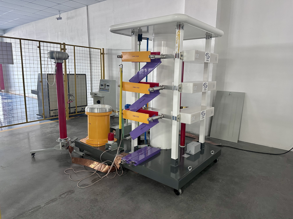
Drawings & test records
List the data sheets, wiring diagrams and test records needed for your project review.
Documents
Downloads
Request the catalogue, wiring diagram and relevant test records.
Go to Download Center →Ordering information
Technical review
Application, installation conditions, control supply and communication requirements.
Documents
Data sheet, drawings, wiring diagram and applicable test records.
Commercial scope
Configuration, quantity, destination, inspection and delivery schedule.
OEM / ODM
Confirm customization, feasibility and approved drawings before production.
After-sales support
Support for your equipment
Contact our team for document clarification, troubleshooting or spare-parts assessment. Support scope is reviewed for your product and project.
Technical assistance
Send the model, nameplate, site conditions and a clear description of the issue.
Spare parts & replacement
Share the serial number, photos and part reference so availability and compatibility can be reviewed.
Project & site support
Training and site-service requests are evaluated against the equipment, location and schedule.
Explore the range
Related products
Technical Support
Frequently Asked Questions
Clear guidance on selection, documentation, customization and project delivery.
What information should I provide for product selection?
Please provide the application, system rated voltage and frequency, continuous load current, short-circuit level, insulation level or BIL, and the required operating duty. Also include indoor or outdoor installation, altitude, ambient temperature, pollution level, control voltage, communication requirements, quantity, destination market and applicable standard. A single-line diagram, existing nameplate or project specification will make the review more accurate.
How do I choose between a recloser, circuit breaker, load break switch, disconnector and fuse?
A recloser is generally used for automatic fault interruption and service restoration on distribution feeders. A circuit breaker provides repeated fault interruption, a load break switch is intended for rated-load switching within its specified capability, a disconnector provides an isolation point, and a fuse provides single-operation overcurrent protection. The final choice must be based on load current, fault level, protection coordination, switching frequency, installation method and operating philosophy.
Which ratings and standards must be confirmed before ordering?
Confirm the voltage class, frequency, rated current, short-circuit breaking and making duties, insulation level, creepage distance, mechanical or electrical endurance, enclosure protection, control supply and auxiliary contacts. The applicable IEC, IEEE, ANSI, GB or project-specific requirement should be stated in the inquiry. The approved data sheet and drawing, rather than only a general product family name, define the final supply.
Can Pomanique help replace existing equipment or confirm interchangeability?
Yes, a technical comparison can be made when sufficient information is available. Please send the existing model and nameplate, general arrangement and mounting dimensions, terminal interfaces, wiring diagram, interlocks, operating mechanism and electrical ratings. Similar voltage and current ratings do not by themselves confirm mechanical or electrical interchangeability, so approval is required before replacement.
How are surge arresters and composite insulators selected?
Selection should consider the system grounding method, maximum continuous operating voltage, temporary overvoltage, required protective level, system insulation level, altitude, pollution severity and creepage distance. Mechanical loading, housing material and installation orientation also matter for outdoor equipment. Provide the system and site data so insulation coordination can be reviewed as a complete set.
Are OEM, ODM and customized configurations available?
Customization can be evaluated according to technical feasibility, validation requirements and order quantity. Typical requests include labels and packaging, terminal arrangements, mounting dimensions, control voltages, transformer ratios, accessories, communication functions and project documentation. Customized production should begin only after the technical specification and approved drawings are confirmed by both parties.
Product Enquiry
For an FTU-R200 quotation, please include:
- Required configuration and communication interface
- Quantity and destination
- Drawings or project specification, if available